Tactile Labyrinth
Presentation
- presentation.mp4 – on the fabacademy.org archive
- presentation video mirror – on youtube
Inspiration
One definition of labyrinth is a winding path with no branches, so if you keep walking in one direction, you cover the whole path and end up back where you started.
I like this aesthetic, and think it would be nice as an object designed for touching.
Noomorph is a made-up word, consisting of noo (thought) and morph (shape). So noomorphology could be a design process that gives shape to thought.
Evaluation questions
Document a final project masterpiece that integrates the range of units covered, answering:
What does it do?
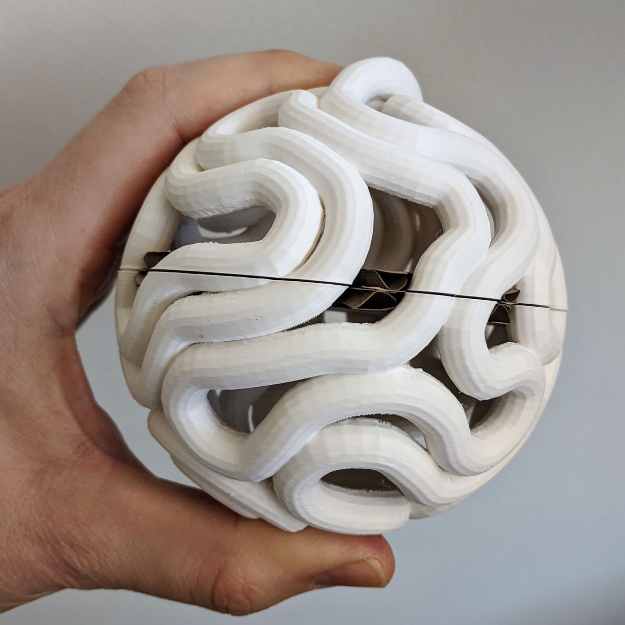
The tactile labyrinth is a 3D path around a ball that can be traced and followed with the hands. Lights along the path are programmed with animations that react to the motion of the ball.
Who’s done what beforehand?
- Michael McGinnis: Perplexus
- Nervous System: coral cup
- Carl Bugeja: Building a Mini Vegas-Sphere
- Ancient: The Fibrovisor
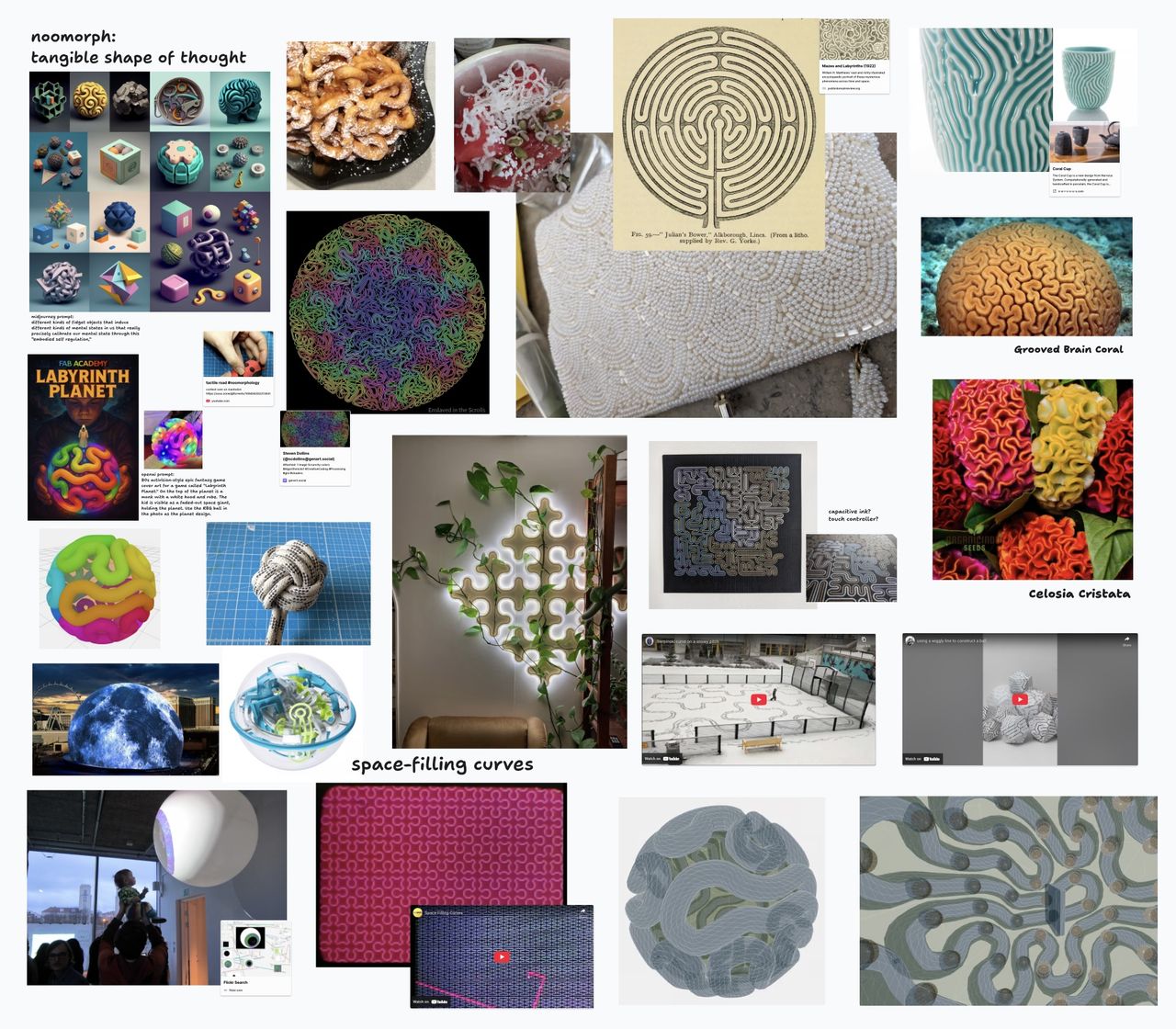
Mood board – interactive version with video embeds and links.
What did you design?
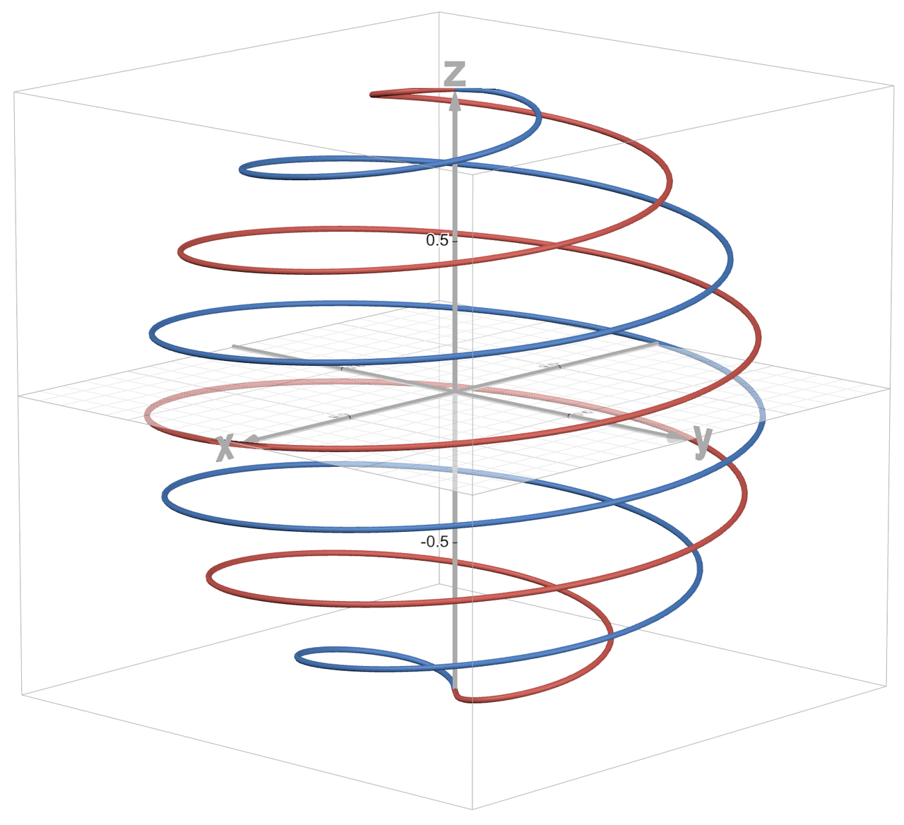
- Parametric design app that simulates a tiny planet and rope loop with self-collisions and gravity.
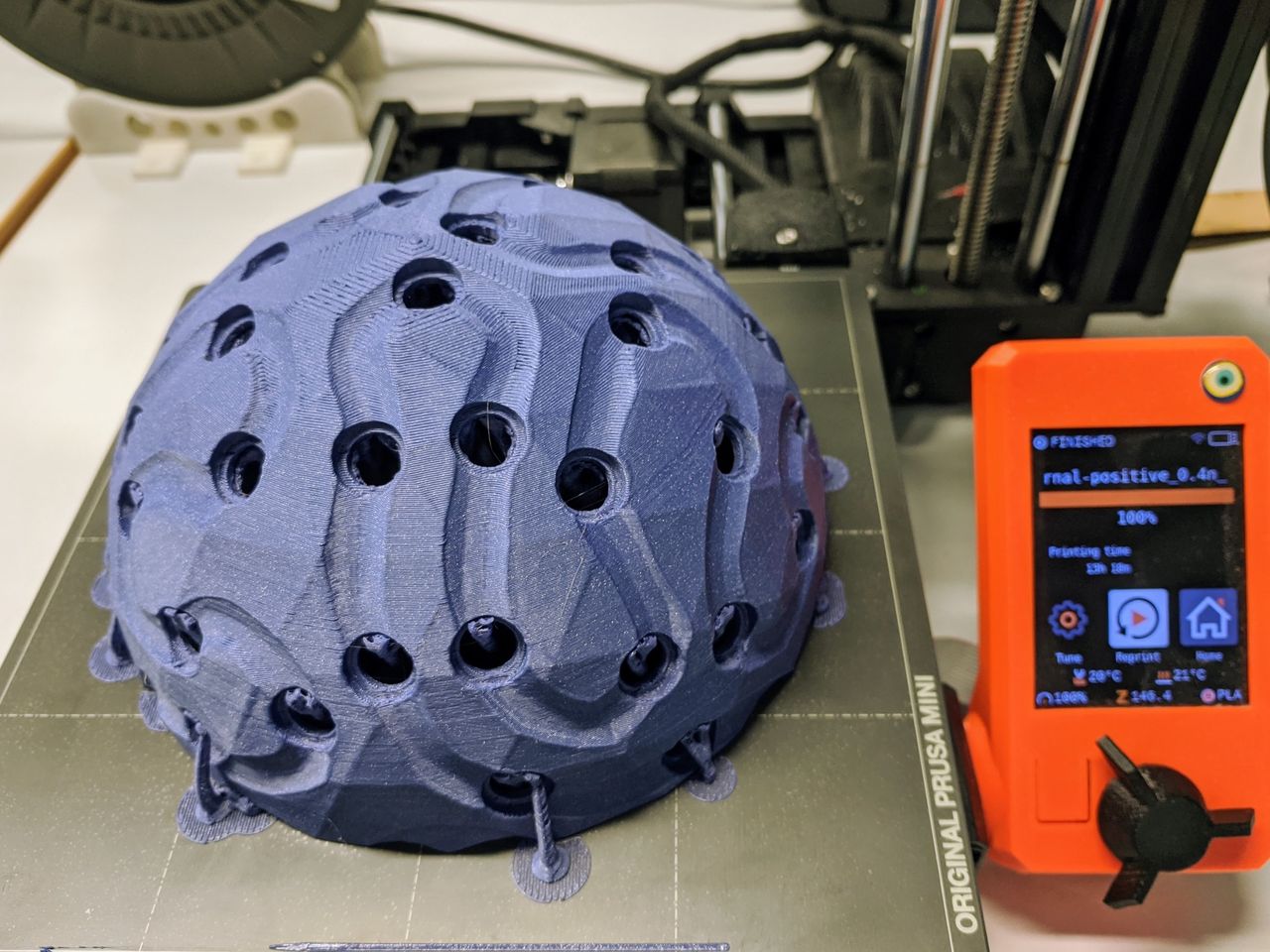
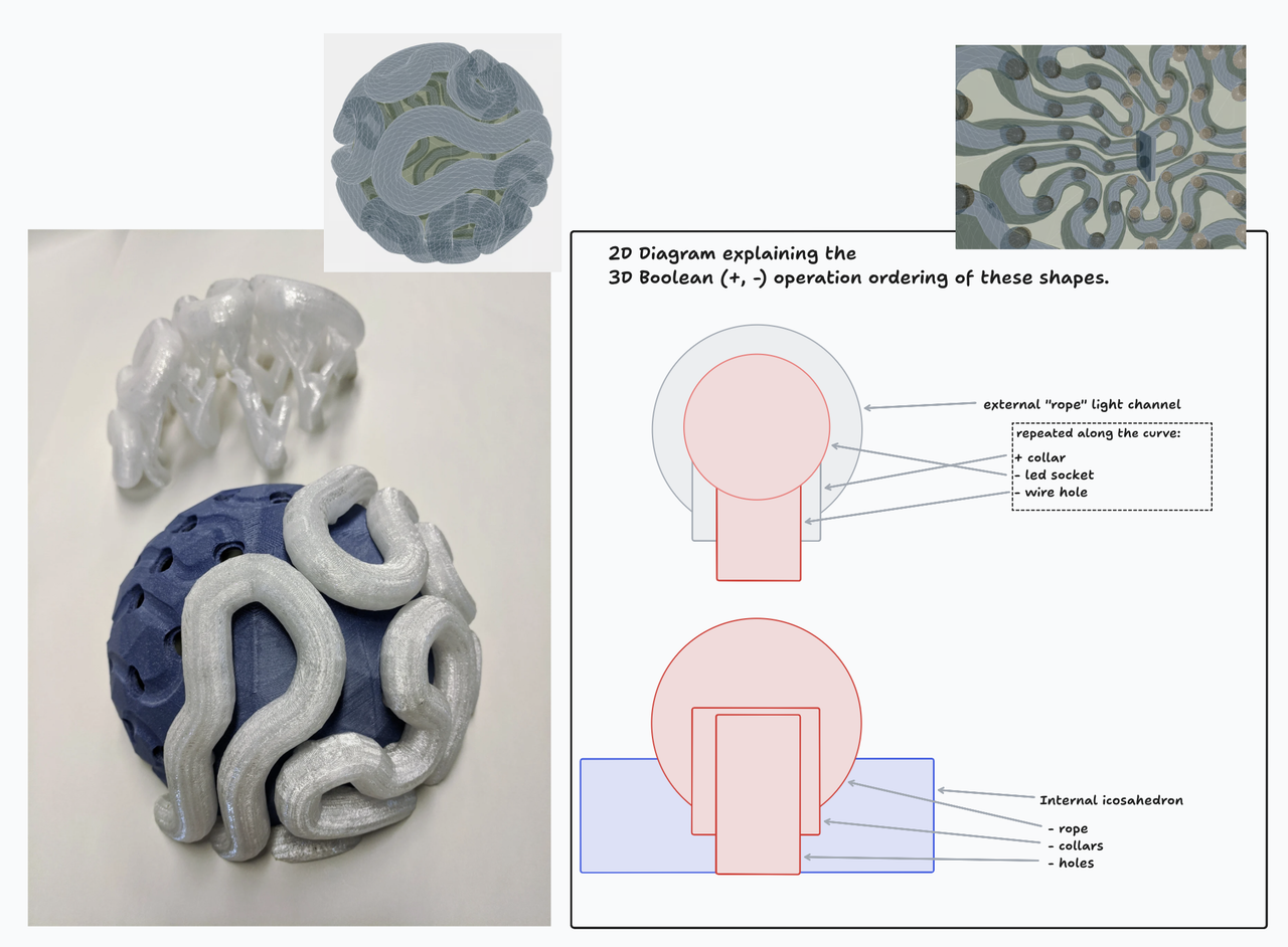
- Once the path is solved, sockets for the LED wires are added, and holes are subtracted, using Boolean operations. The sockets are oriented towards the center of the ball.
- The app exports positive and negative space STLs that are combined in Blender or Prusa Slicer before 3D printing.
- The parts snap together securely, mostly without glue.
- The LEDs are inserted into each socket. The wire loops through the inside of the ball.
- A platform sits between the halves of the ball. It was designed to keep the accelerometer at the center of the ball, and the battery close to the center of gravity.
- Arduino code interfaces Adafruit accelerometer and FastLED libraries.
What sources did you use?
- 3D Singh VFX Blender Geometry Nodes tutorials
- Claude Sonnet 3.5, 3.7, 4 via readme-based development
- Adafruit accelerometer library
- FastLED library, especially the "rainbow" balanced color functions
What materials and components were used?
Where did they come from?
How much did they cost?
| maker and part | part number | source | cost |
|---|---|---|---|
| Seeed Studio XIAO RP2040 | 102010428 | Digikey | $4.68 |
| Adafruit LSM6DSOX 6 DoF Accelerometer and Gyroscope - STEMMA QT / Qwiic | 4438 | Digikey | $11.95 |
| Texas Instruments 3 V to 5 V Level Shifter | TXB0104DR | Digikey | $0.92 |
| Horizontal SMD 2.54mm pitch pin socket connector (01x04) ($0.67 * 3) | BG300-04-A-L-A | Digikey | $2.01 |
| Horizontal SMD 2.54mm pitch pin socket connector (01x03) | BG300-03-A-L-A | Digikey | $0.51 |
| 7 Position vertical header ($1.08 * 2) | NPTC071KFXC-RC | Digikey | $2.16 |
| Omron push button switch | B3SN-3012 | Digikey | $0.71 |
| YAGEO 4.99 kOhms resistor 1206 ($0.10 * 2) | RC1206FR-074K99L | Digikey | $0.20 |
| TDK Corporation 0.1 µF Ceramic Capacitor 1206 ($0.23 * 2) | C3216X7R2A104K160AA | Digikey | $0.46 |
| Bantam Proto Board Copper Clad FR1, Single Sided ($67.53/25) | MT1004 | Digikey | $2.70 |
| BTF-Lighting WS2812B 10m / 100 LED String | btf-5v-100l-t | Amazon | $16.99 |
| Filalab transparent PCTG filament ($28.50/kg, 537g) | 4779051441044 | Filalab | $15.30 |
| Filalab Galaxy Blue PLA filament ($22.80/kg, 351g) | 4779051440993 | Filalab | $8.00 |
| Clas Ohlson 5000mah battery bank (generic versions of the product exist) | 39-3976-1 | Clas Ohlson | $28.46 |
| Baltic birch plywood, 3mm (128mm square, from offcut) | Fablab | $2.00 |
Total: $97.05 USD (€85.06 EUR)
What parts and systems were made?
- 3D printed parts for the inner case (opaque) and LED path (transparent)
- Laser cut mounting platform for circuit boards
- Custom circuit board
What processes were used?
- 3D printing
- Laser cutting
- CNC milling for the circuit board
What questions were answered?
Can I make a path from a physics simulation, embed addressable LEDs into the path, and program a microcontroller to make interactive color animations on the object? Yes, I can do those things now.
What worked? What didn't?
See LED strip drama in the build log for something that did not work. Also the first attempt at soldering the circuit board (Week 08) did not go well.
The fit between in the inner outer parts worked better than expected. I thought it would require more iteration, but the first version worked as the final.
Otherwise, things worked out pretty well.
How was it evaluated?
Local and global evaluators for my weekly documentation.
Friends and family birthday party, play-testing with folks young and old. Their hands are in my presentation video.
Helsinki Media Lab Demo Day, passing around the labyrinth and speaking with people involved in new media art. It was nice to run into former teachers and fellow students, and to just place the object into their hands to see their reaction. One described the gameplay as "homeopathic" which I appreciated.
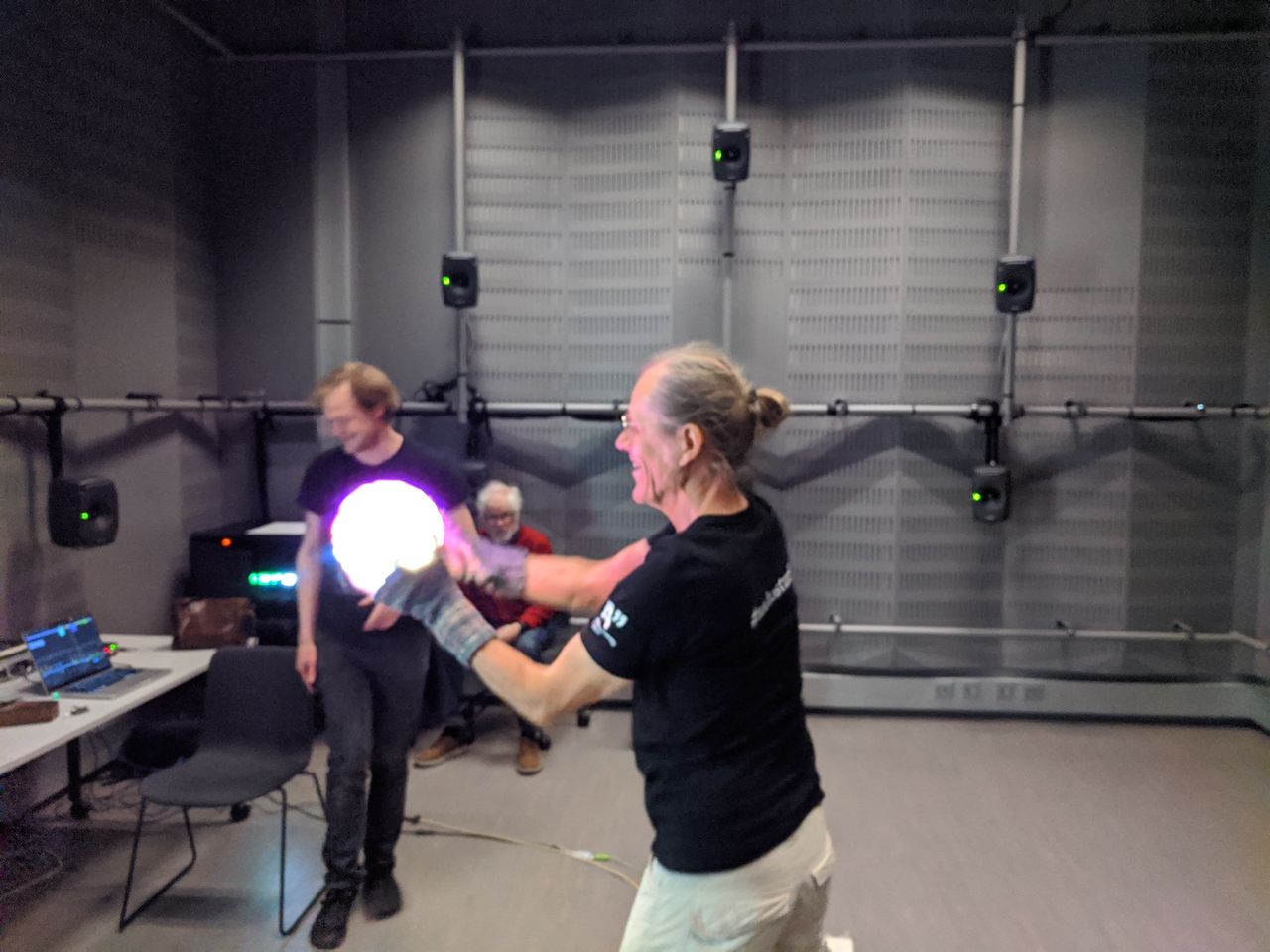
At demo day. Playful spontanious combination with a 360° audio installation.
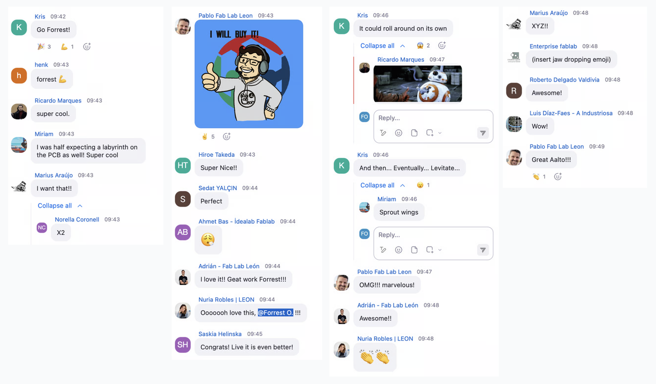
Fab Academy final presentation comments. Thank you all. 😊
Neil suggested that I add more about the physics simulation.
This version is 180mm in diameter and 800g. In my next steps I have been thinking that a target for the next version would be half the size and weight, to be easier to pick up, transport, and manipulate. But at least two play-testers said that they appreciate the size and weight as it is. It certainly feels substantial.
Social media
To share with the wider web I posted my presentation on YouTube, Mastodon, Bluesky, Instagram, and linked back to here. I didn't get a lot of feedback on those sites. I think it's more interesting in person... considering the title of the project, that makes sense.
What are the implications?
My goal in joining Fab Academy was to expand the tools and processes in my digital fabrication toolbox. Coming in to the class, I was comfortable with 2D design and laser cutting. Taking an earlier project that was static and 2D, and making it interactive and 3D, is a good reflection of all that I have learned in this class.
Build Log
The rest of this page was updated through the course as I worked on the labyrinth.
Previous work
"Wave Form Collapse" seeded random labyrinth, 2018.
"Folding powers of 2" labyrinth, pen plotting, 2021.
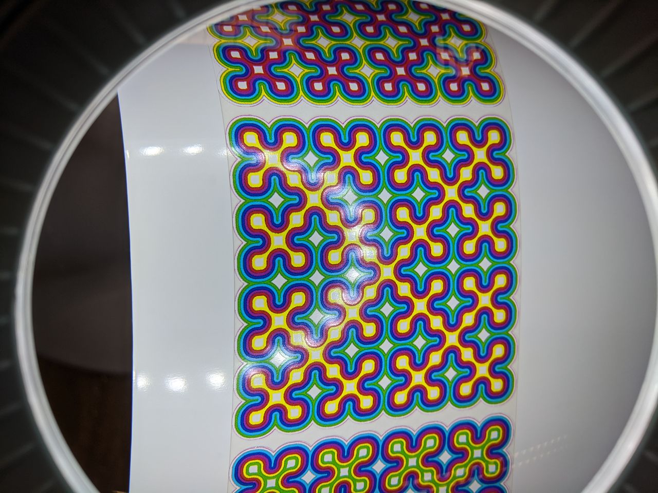
Stickers made during fab Week 03.
More Sierpiński curve projects: snow walking, wall lamp, web animation, 3D print.
2D wooden labyrinth, 2018.
Sketch for a 3D wooden labyrinth.
Simulation
Both the Blender and web versions of the simulation include a center of gravity, a ground sphere, and a loop of beads. Each frame of animation can have many physics cycles, that advance the time a fraction of the animation frame time. I use Verlet integration to solve the positions of an velocities of the beads that make the rope.
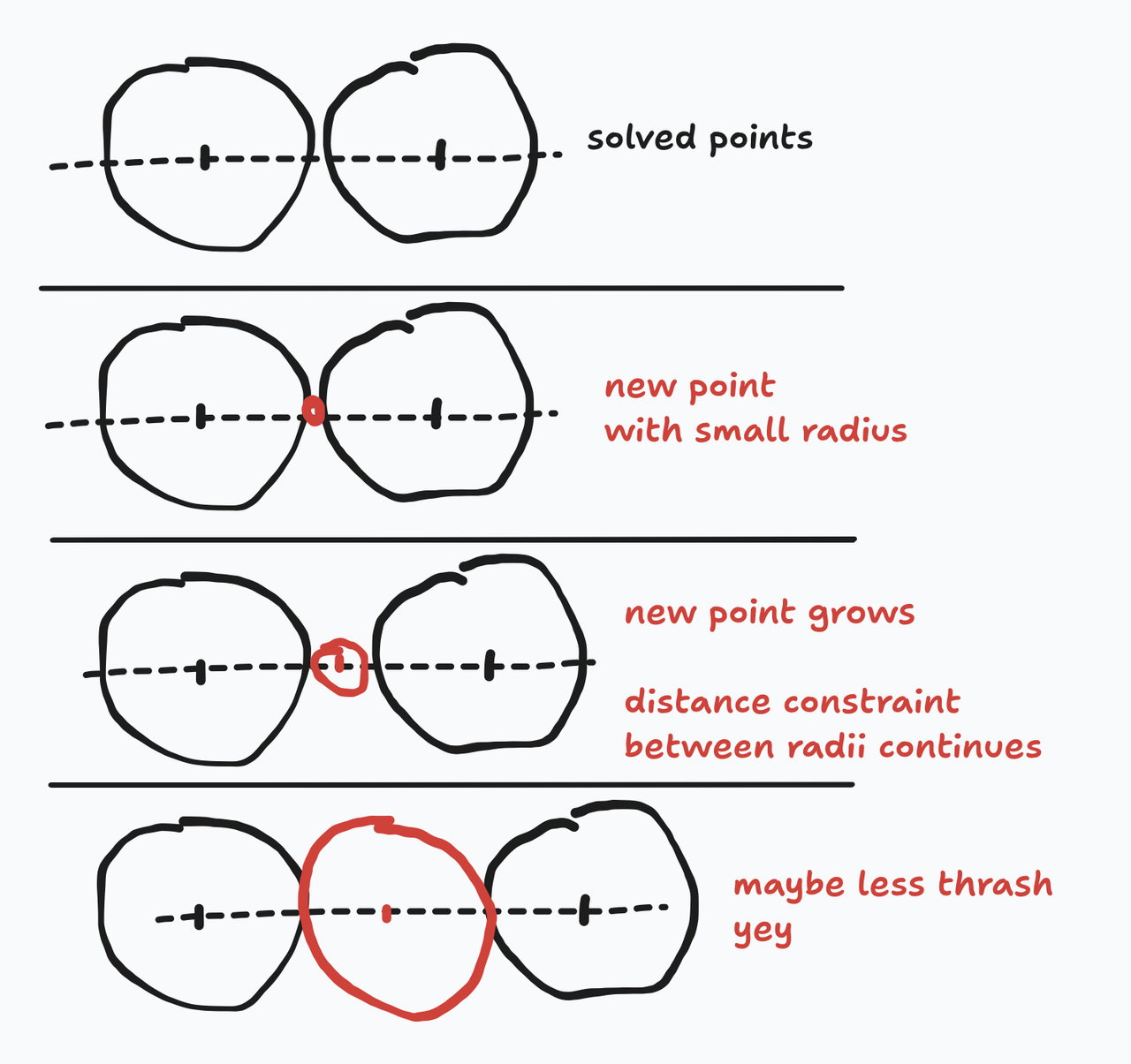
One challenge was smoothly adding beads to the rope. If you just add a new bead between two existing ones, the new bead will be overlapping, and the collision constraint will "thrash" the rope as the beads jump away from their overlap. By adding a new bead with a small radius and then smoothly growing it, the rope can grow without this thrash.
Blender geometry nodes
Ropes simulated in Blender. I have a Blender journal that documents that simulation.
With this simulation, I can grow irregular paths around any shape, with various paramters like center of gravity.
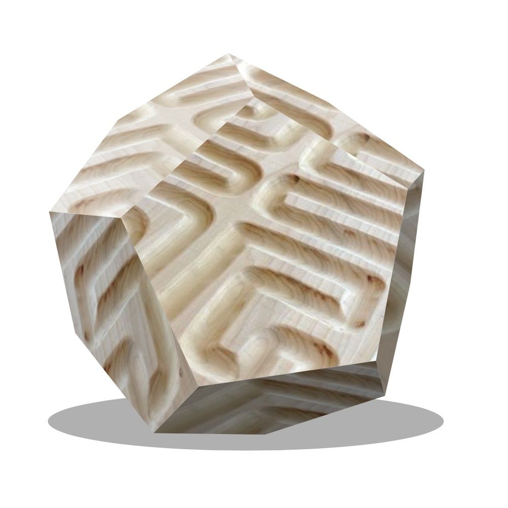
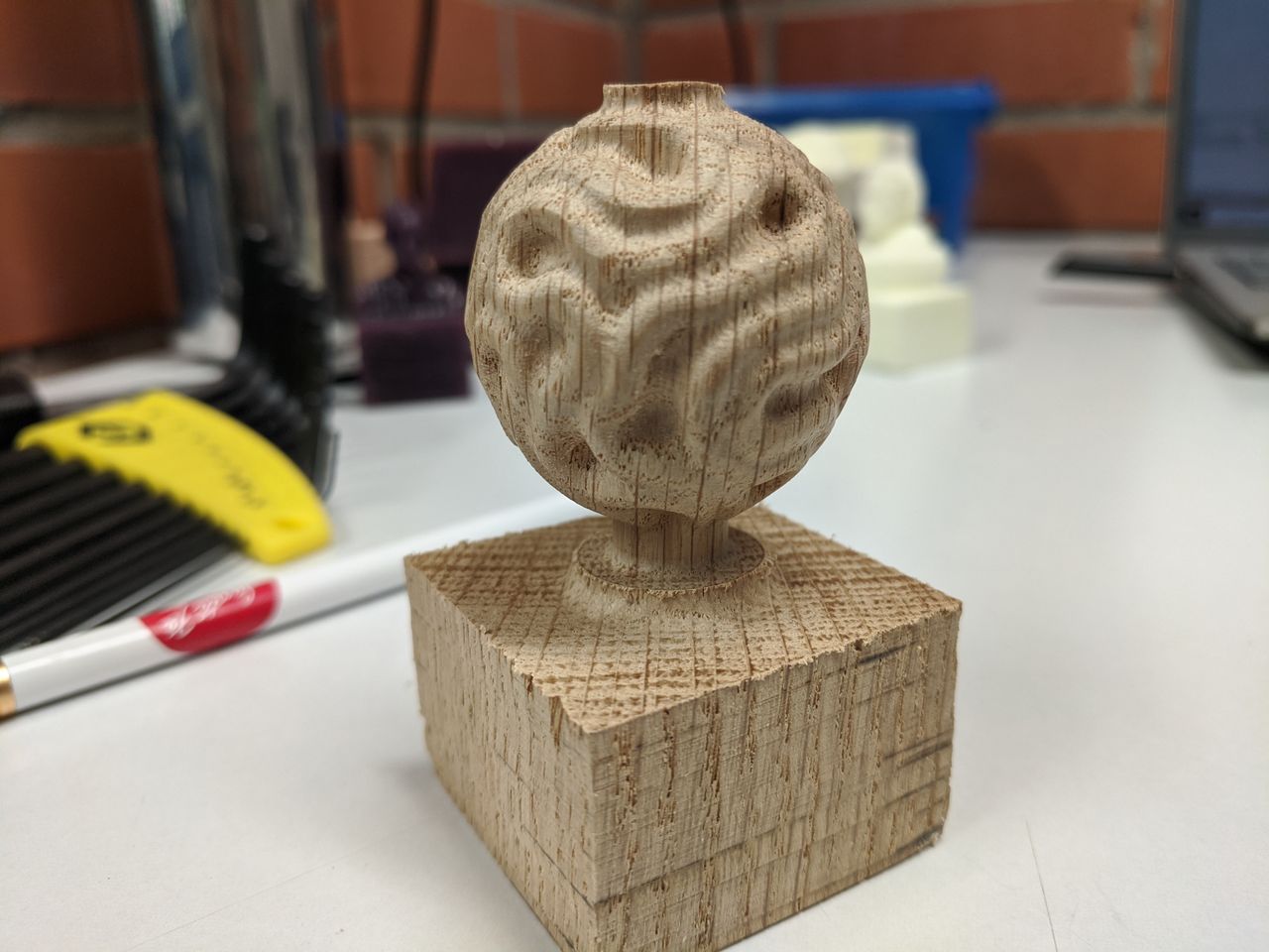
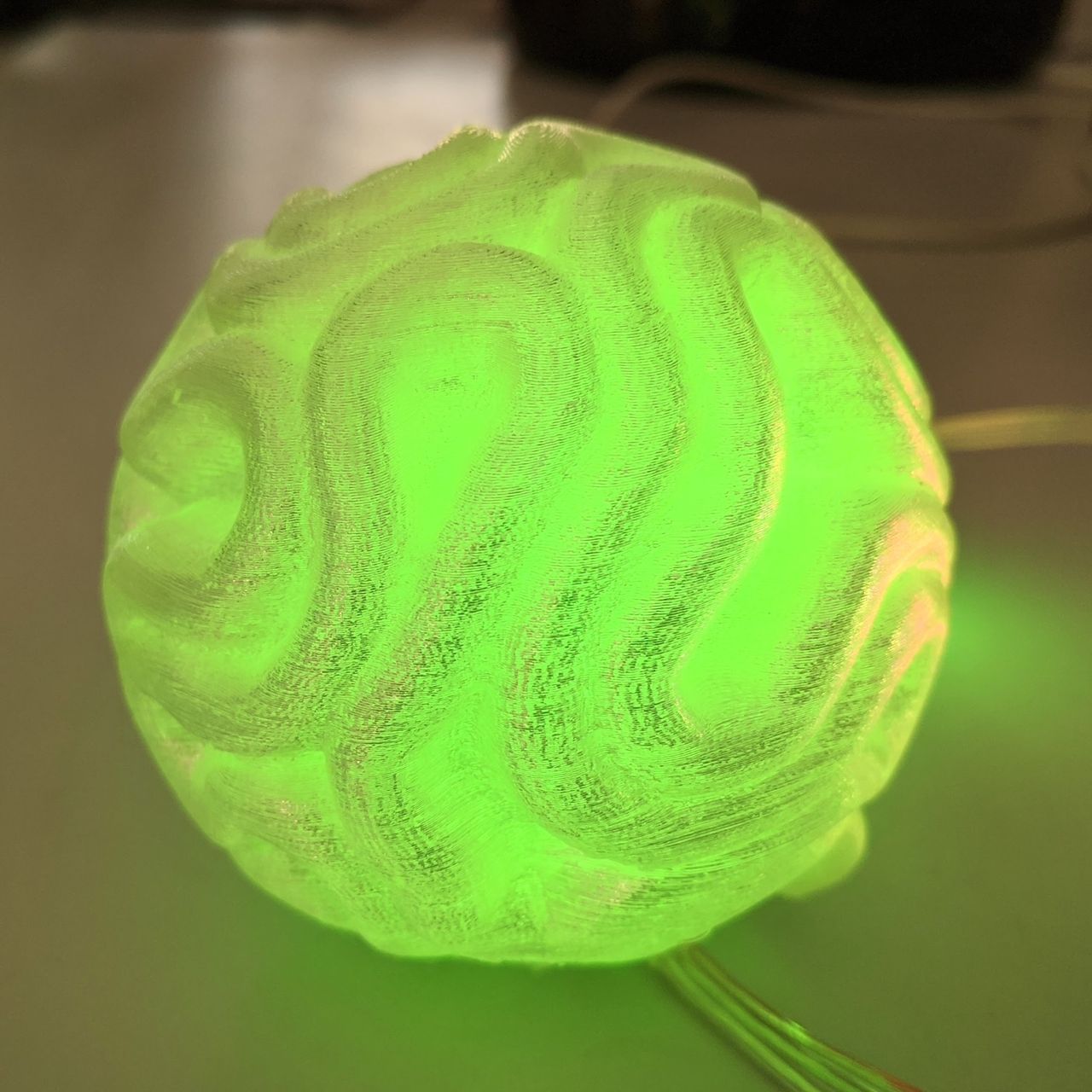
3D embed, union of simulated ropes and base icosahedron.
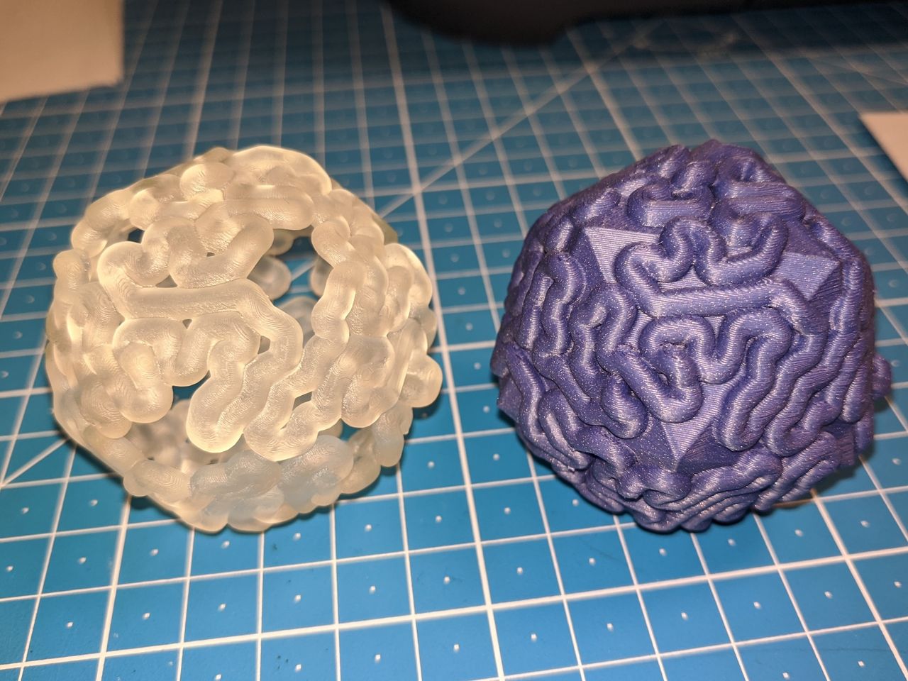
I've printed 3 versions of the same simulation result: ropes only, union with icosahedron, and difference (carving into the polyhedron). There is a pleasing contrast between the regular polyhedron and organic ropes.
Web
I ported the Blender geometry nodes rope simulation to the web, with help from Claude 3.7. I structured the prompt as a readme file, but it took a bunch of iteration to reach parity with the Blender version. I lost Blender's fancy rendering, but gained live parameter tweaking and more direct manpulation and interactive possibility.
Interaction
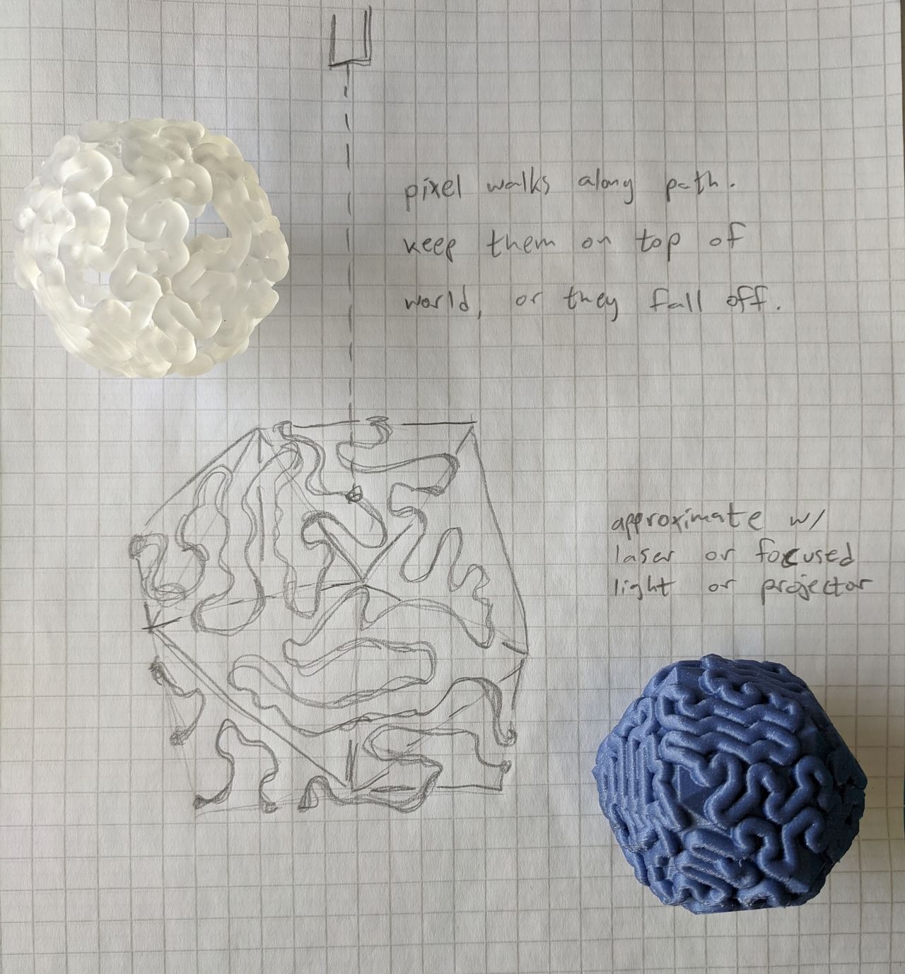
Idea for a game-like interaction, where a character, represented by one LED of the string, walks along the path, all around the sphere. You have to turn the ball to keep them on top.
Maybe the bottom hemisphere stays blue and sloshes around a bit, to represent water.
Large scale prototype
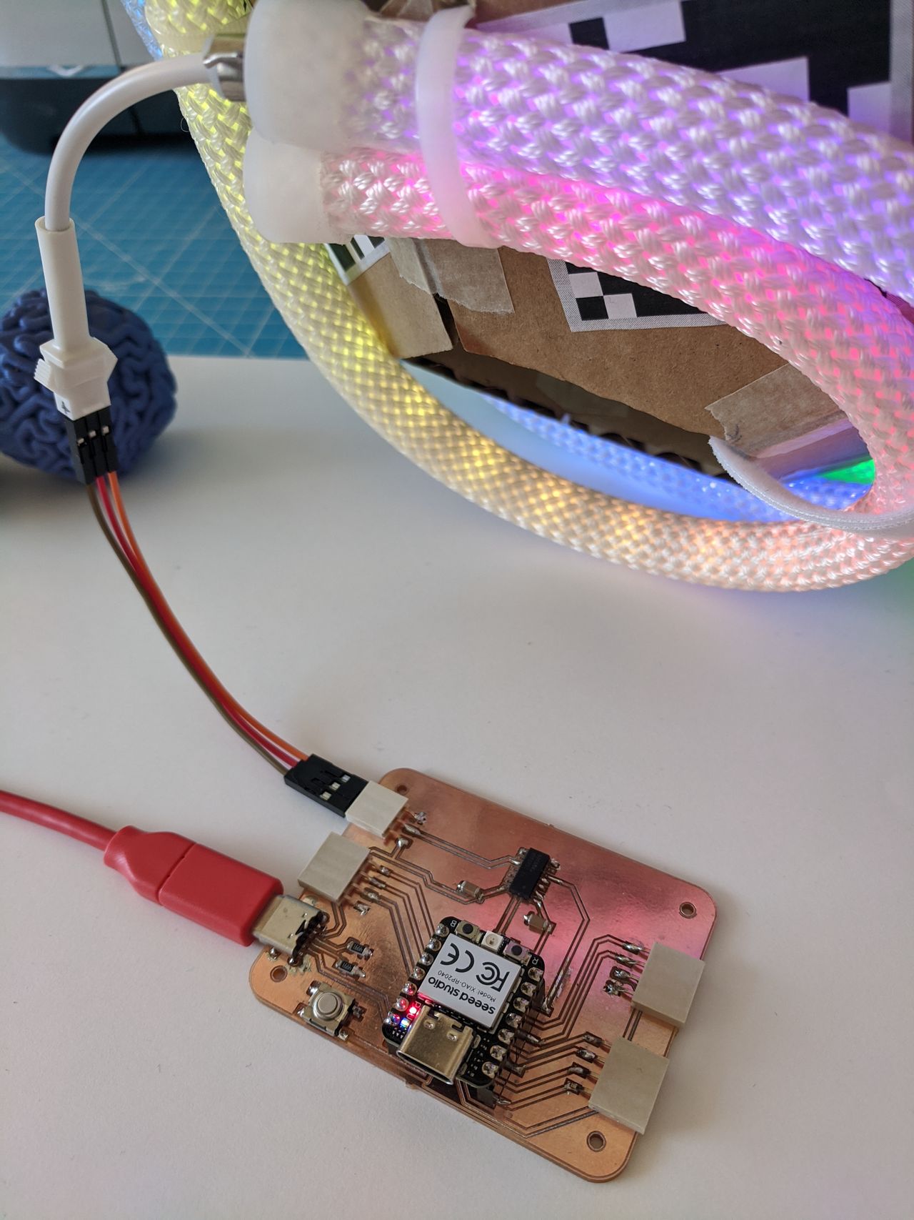
I bought an addressable LED "rope" with USB power, animation controller, and silicone and nylon diffuser.
By wrapping it around a ball, we could start to get a sense of how it would feel to hold an animating light orb. But I needed a better structure to attach the rope.
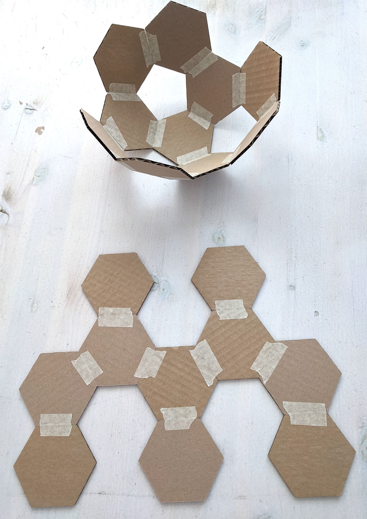
Everybody should have a stack of cardboard hexagons handy. This is actually the third life of these hexagons. They started as offcuts of a laser cutting jig, then became prototype game pieces, then became apriltag tokens for Folk Computer.
Cardboard soccer ball ready, a.k.a. truncated icosahedron.
With some zip ties to attach the LED rope. Getting a feel for the form, imagining a mag sensor driving the light motion.
Circuit design
Documented in week 10's post.
Future iterations ꩜
Mirror image prints, to trace with fingers in each hand.
3D modeling: learn how to split shape to be printed as triangles flat on the bed.
CNC carving: translate that design to be carvable.
Electronics: make it possible to insert LED rope, design animations that fit the form.
Open questions
- What is the interaction?
- If I end up with an unconventional display, what will it show?
- Could it be the base of the "calm timer" idea?
- Can I keep the tactile inspiration while adding electronic interactivity, or are those exclusive?
Midterm plan
Desmos graph with approximate LED path. Time to "eat the frog" and do some integration. The step I've been a little stuck on is mapping the LED indexes to positions. By making an formulaic approximation, I can get something on the microcontroller to get unstuck, and finesse the strategy later.
2025-04-23: Week 13's post.
Prototype integration
It's important to get my hands on a working version, the integrated cardboard prototype, to better understand how to budget the rest of my time. What are the most important improvements to make in each area of the build?
Sensor and animation
I really want to get the sensor and battery in position now!
Battery and sensor position
Wireless and handheld at last.
(Re)calibration app
![]()
2025-05-07: Once I had a version with the accelerometer in place, I reworked the calibration flow. Week 15's post.
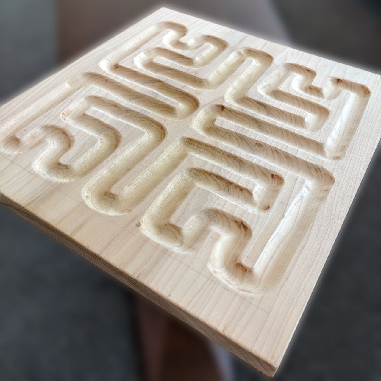
Wood side quest
Four axis milling for wildcard week 17.
Final integration
Material choice
Material and LED socket tests in week 16.
Boolean workflow
Internal structure design and printing the major parts.
Aesthetic
I'm committed to the "3D print of medium poly count geometry" aesthetic now. Other processes and sanding didn't enhance the tactile or translucent qualities that are important.
3D print snap-together
An accident, but my test parts became my production parts when they snapped together real nice. But why did it work out that way?
Hemisphere coupler
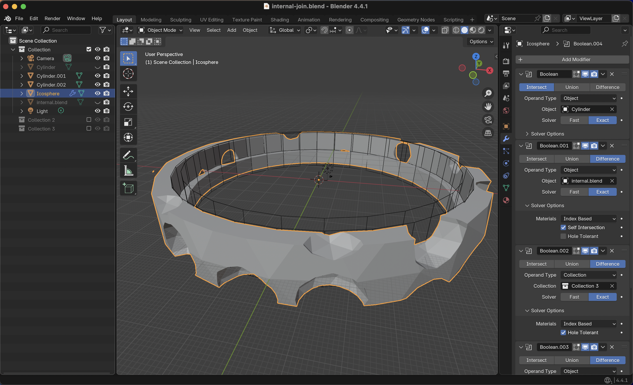
Blender setup for the part that holds the two hemispheres together. Part created with several Boolean modifiers.
Circuit mounting platform
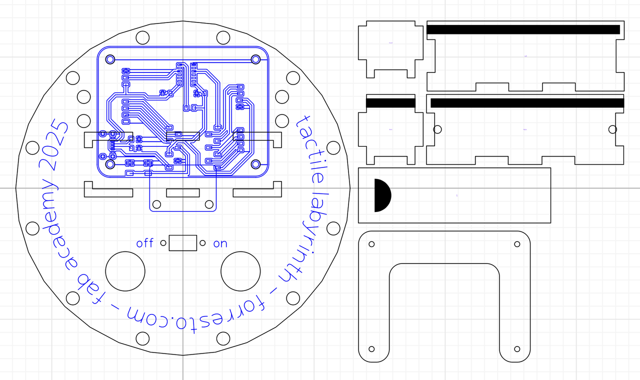
The platform is designed to put the accelerometer at the center of the sphere, and the 18650 battery compartment near the center of gravity.
Week 18: documenting these final parts.
RIP LED index 0
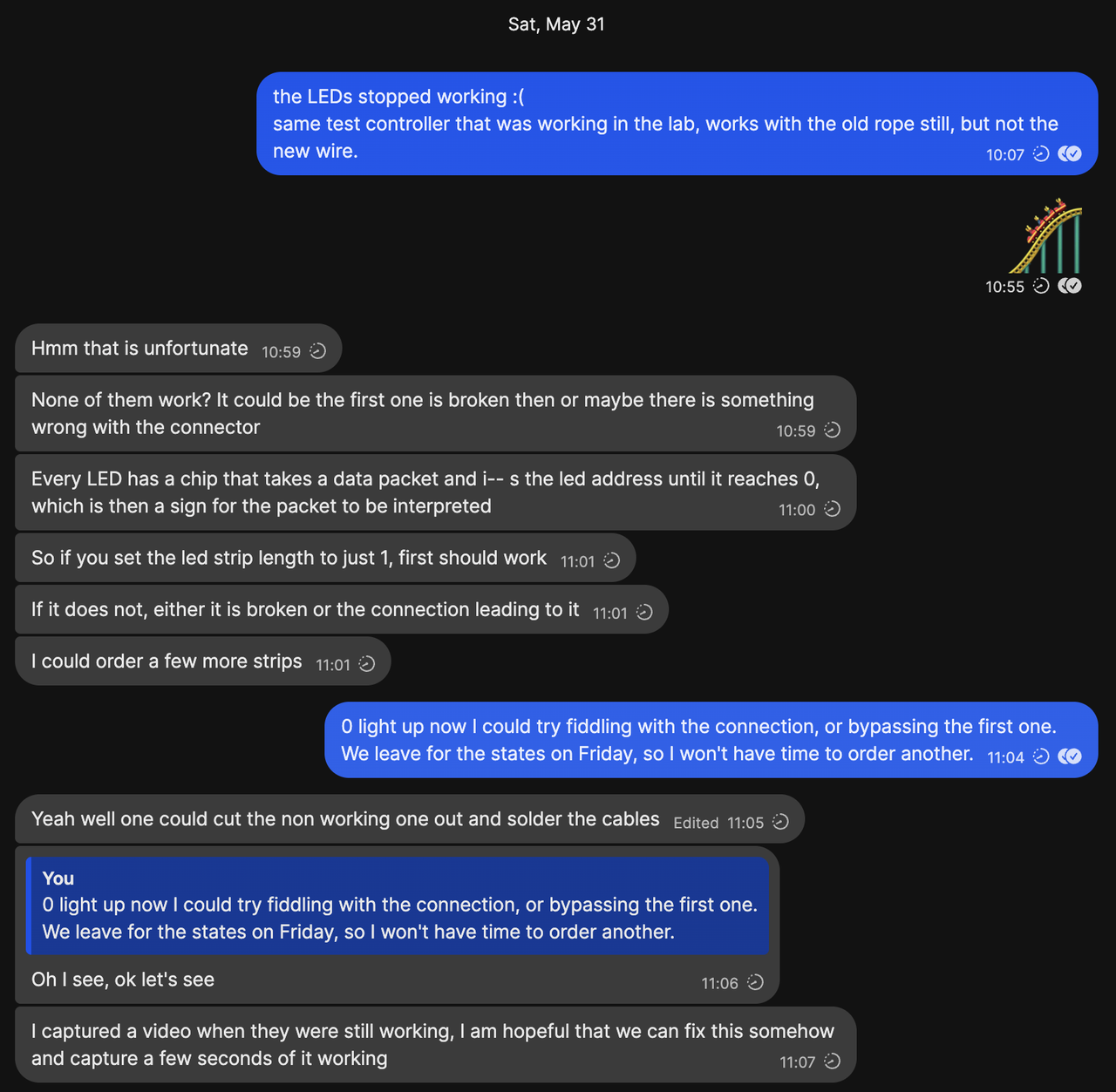
After feeling lots of momentum at the lab getting the parts produced and integrated, I took everything home to finish the integration. I was distrought when none of the LEDs worked. I tried various controllers and power supplies, and they worked with another LED strip, but not my wire. I couldn't find a local source of the LEDs, and it would take too long to get a replacement. I thought my schedule was shot. I wouldn't be able to finish the course on time.
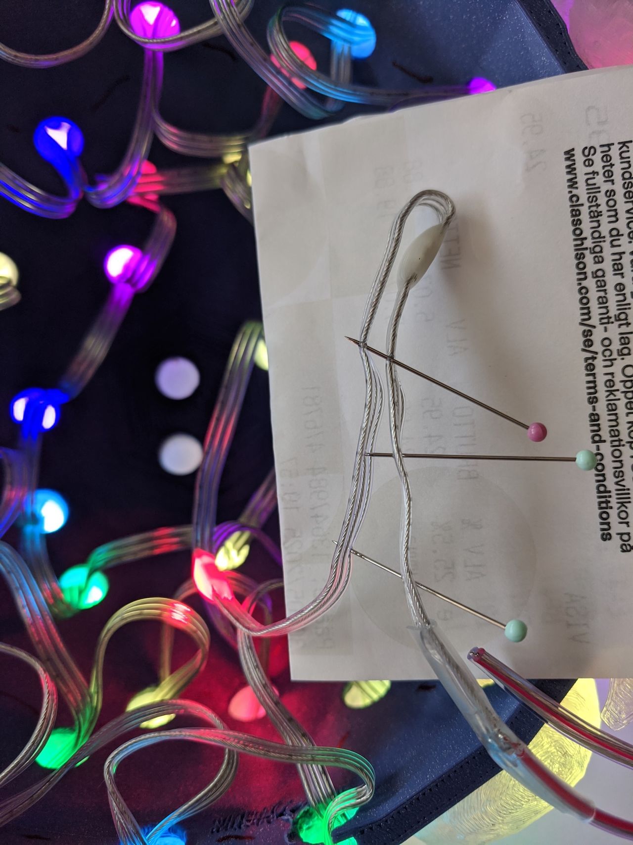
Kris mentioned that if something happens to the first LED, it might not forward the signals needed to the rest of the strip. Instead of cutting it out, I tried jumping the 3 wires with sewing pins. I was shocked and elated when it actually worked.
What a roller coaster. 🎢
One LED can make the whole string not work, and the string not working made me think that the whole project wouldn't be done. In that way, it was a self-analogy of dependency failures.
Software integration
The gist of calibration:
- Light one LED at a time
- Turn the ball to put that at top
- Record the gravity vector for that LED
I also had to make an array mapping the outer path LED order to the internal index, because the order is different.
readme.md for the final software.
Source
forresto-tactile-labyrinth-v0.zip
.
├── dev_board
│   ├── dev_board.kicad_pcb
│   ├── dev_board.kicad_pro
│   └── dev_board.kicad_sch
├── print-and-cut
│   ├── internal-join-v2.stl
│   ├── internal.blend-bottom.stl
│   ├── internal.blend-top.stl
│   ├── labyrinth internal support - cuttle.xyz.svg
│   ├── rope-3d-print-complete-2025-05-27T10-48-23-285Z-negative.stl
│   └── rope-3d-print-complete-2025-05-27T10-48-23-306Z-positive.stl
├── TactileLabyrinthFinal
│   ├── PixelBallLedMap.h
│   ├── readme.md
│   └── TactileLabyrinthFinal.ino
└── web
    ├── lib
    ├── pixel-ball
    │   ├── index.html
    │   ├── pixel-ball-initial.js
    │   ├── pixel-ball-viz.js
    │   ├── pixel-ball.js
    │   └── readme.md
    └── rope-simulation
        ├── generated
        │   ├── main.js
        │   ├── Physics.js
        │   ├── Print3D-worker.js
        │   ├── Print3D.js
        │   ├── Rope.js
        │   ├── RopeVisualizer.js
        │   └── TubeSDF.js
        ├── index.html
        ├── lib
        ├── readme.md
        └── rope-148-16.json
fab license
© Forrest Oliphant 2025
This work may be reproduced, modified, distributed, performed, and displayed for any purpose, but must acknowledge "Tactile Labyrinth by Forrest Oliphant". Copyright is retained and must be preserved. The work is provided as is; no warranty is provided, and users accept all liability.
Example acknowledement link in markdown:
[Tactile Labyrinth by Forrest Oliphant](https://www.forresto.com/fab-academy/tactile-labyrinth.html)Next steps...
Hardware upgrades:
- Break out small panel for external access for power switch, charging, programming
- Improve the joinery of the halves of the sphere
- Fancy compound hinge?
- Vibration motor with satisfying feedback for the gameplay
Software:
- Gameplay improvements, make the motion more connected to physics
- Persistence of vision, show images when spinning or throwing the ball
- ← Previous
Week 18. Final Labyrinth Parts