Week 18. Final Labyrinth Parts
This week I continued the materials tests from week 16 for the tactile labyrinth. I also refactored the rope simulation web app to export STLs for the internal structure of the labyrinth.
Inner parts
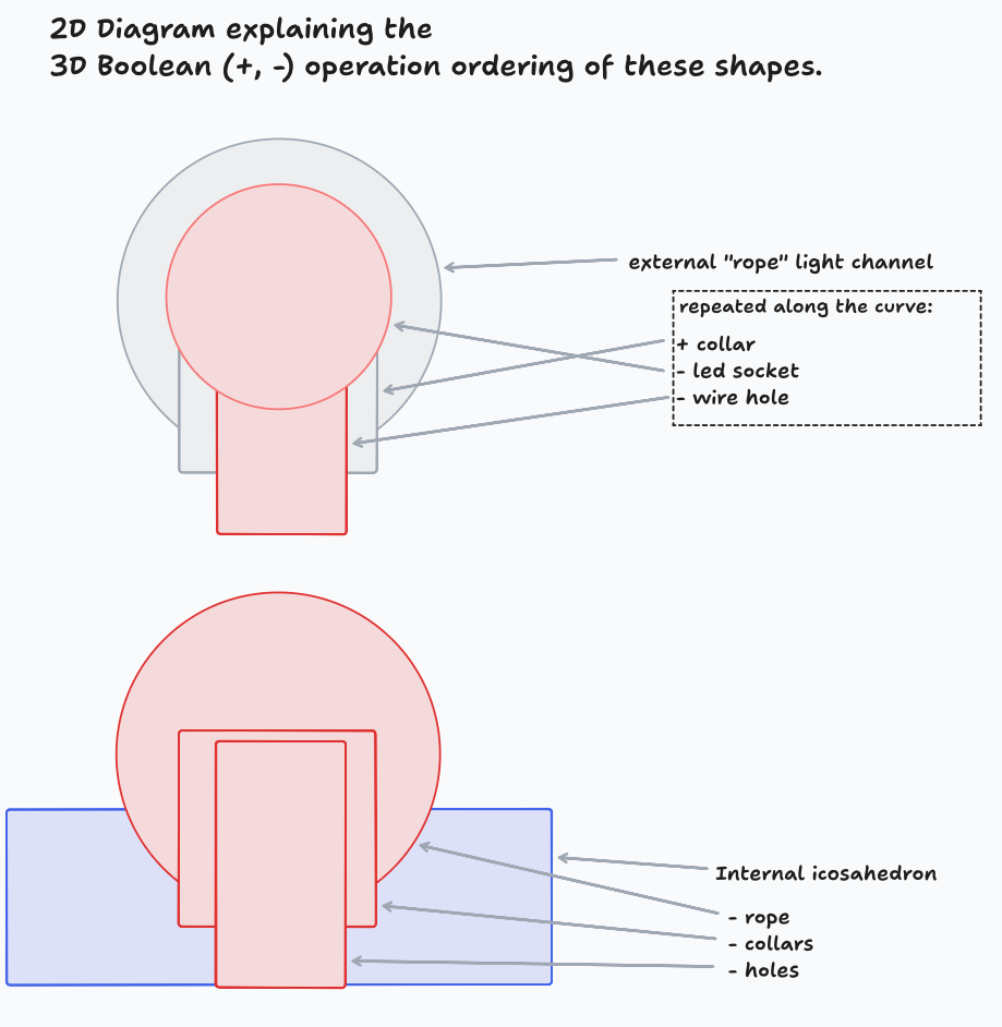
As booleans on organic shapes are heavy in the browser, I continued with the positive/negative STL export process that I outlined in week 16.
When slicing the second half of the internal structure, I ran into a bug with Prusa Slicer that would discard some of the geometry. I had to recreate boolean operations in Blender, but now I have actual STLs for the parts that don't depend on Prusa Slicer.
This design is a callback to an earlier version that combined the geometric lines of an icosahedron with the organic path of the rope simulation. The main purpose is to be a structure for the outer parts and electronics, It also hides the wires and prevents accidental poking from the outside.
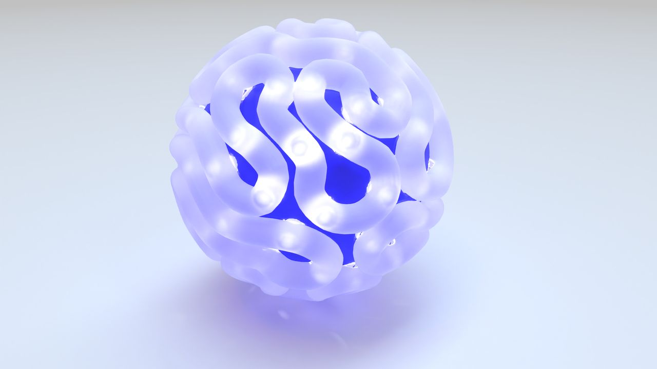
Renders
3d embed.
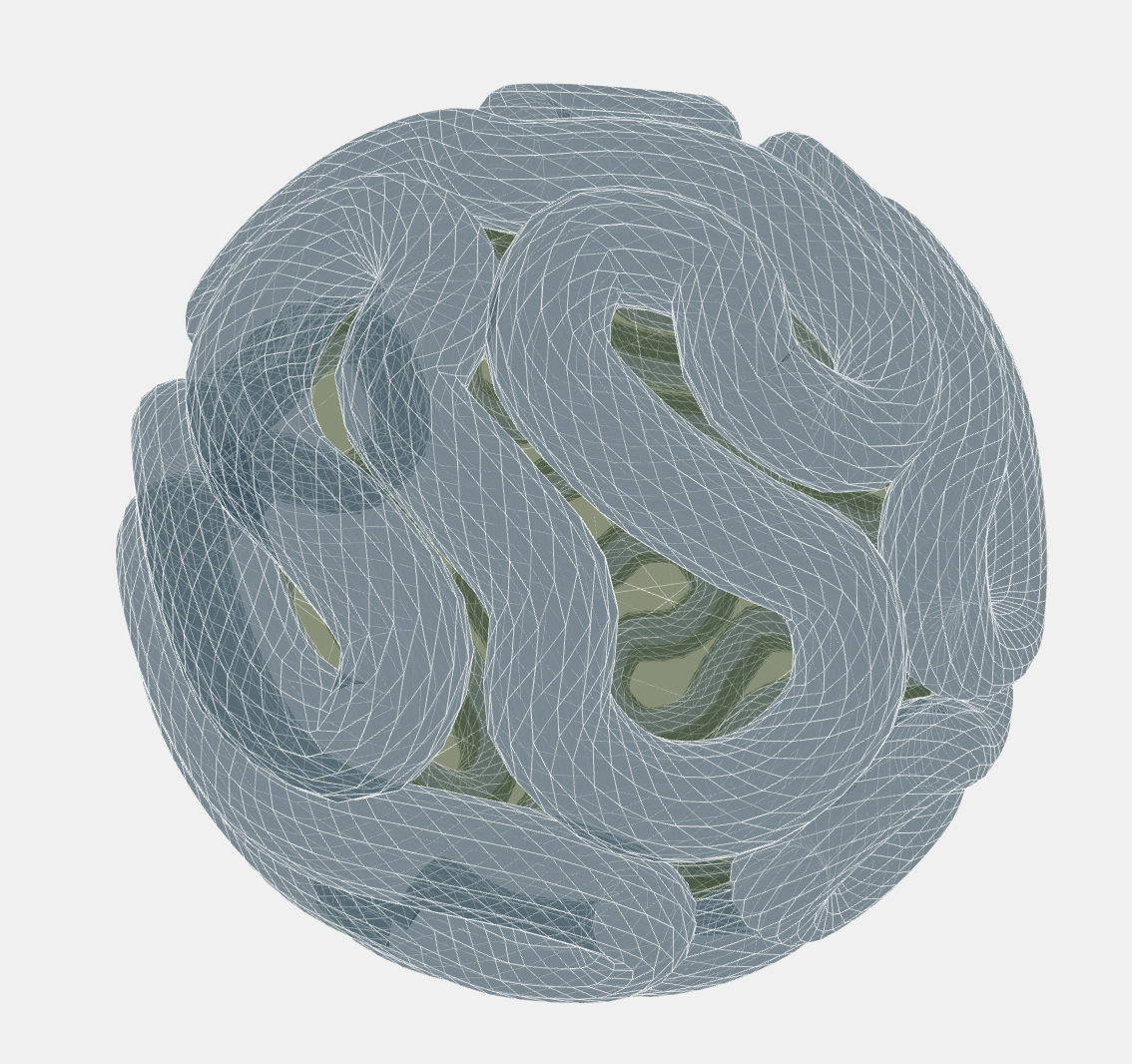
New Three.js materials for preview.
Parts imported to Womp to play with their rendering. I thought that it might be good for some final modeling on the parts, but they can't import editable meshes with full fidelity. I'm committed to the "3D print of medium poly count geometry" aesthetic now, so Womp's SDF modeling would be a step away from that.
Outer parts
Because I adopted an internal structure, I made a physics constraint tweak is that the rope should not merge into itself. This will make the rope parts individually printable, and keep light from leaking through the unioned areas.
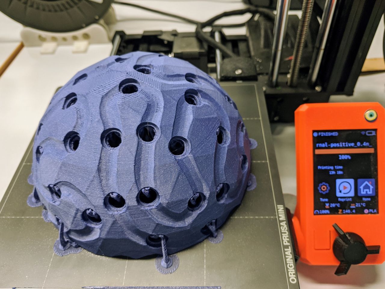
I continued the material tests of week 16 by trying Formlabs Transpanent Resin v4, and Fiberology Transparent PCTG. The resin print is the most transparent, but I'm depending on the light diffusion of the filament 3D printer and infill, so I'll continue with that.
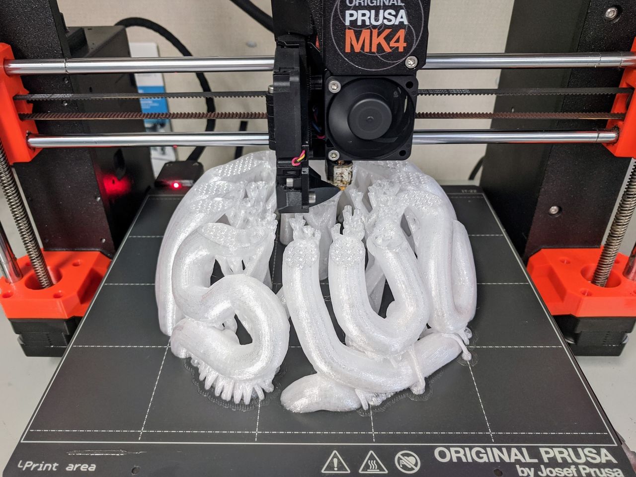
21 hour print.
Could experiment with more-efficient bed placement of the rope parts.
3D print snap-together
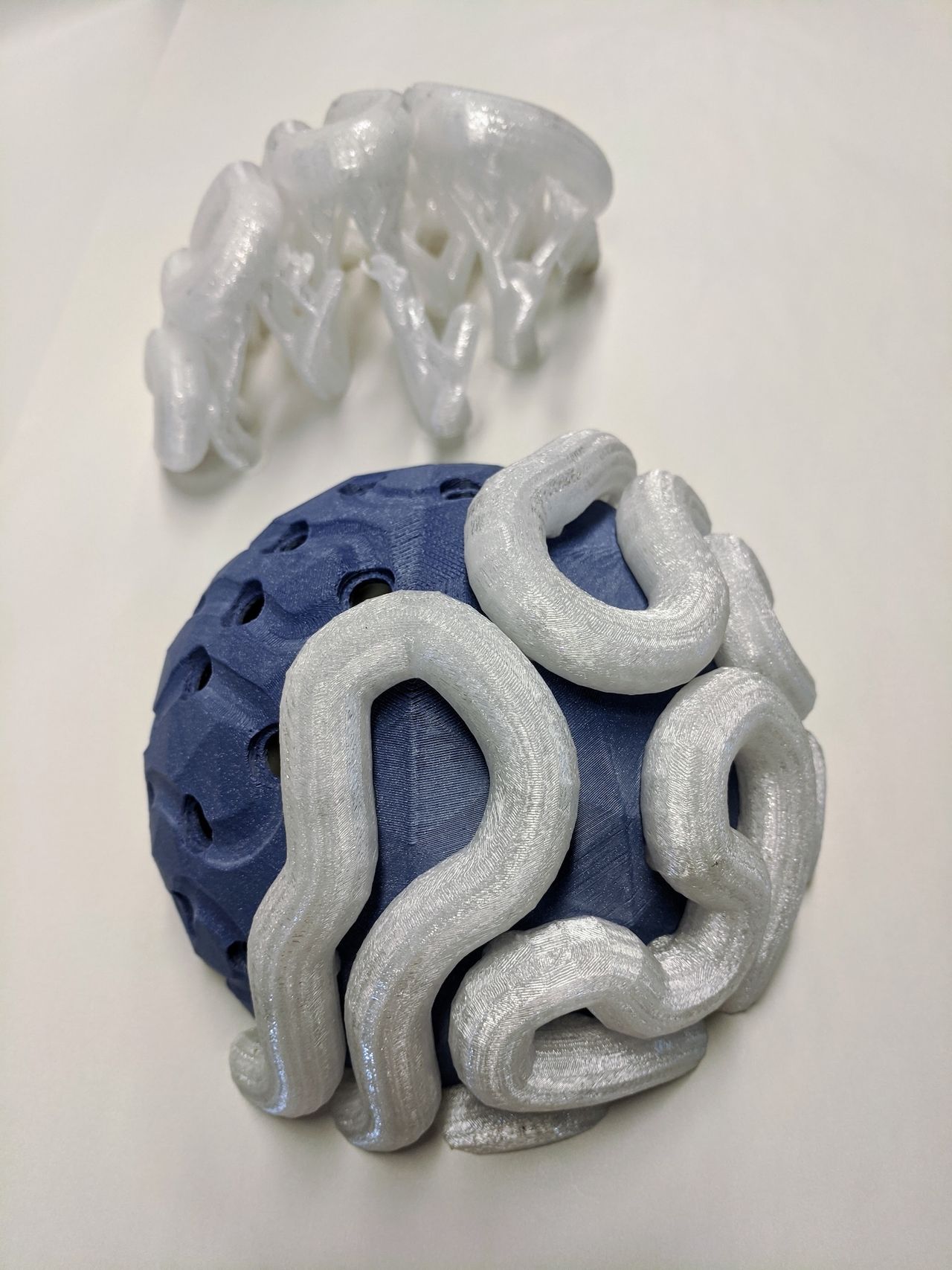
An accident, but my test parts became my production parts when they snapped together "real nice".
Somehow these two prints with similar settings and different materials and no "kerf" compensation snapped together in a really sturdy-feeling way.
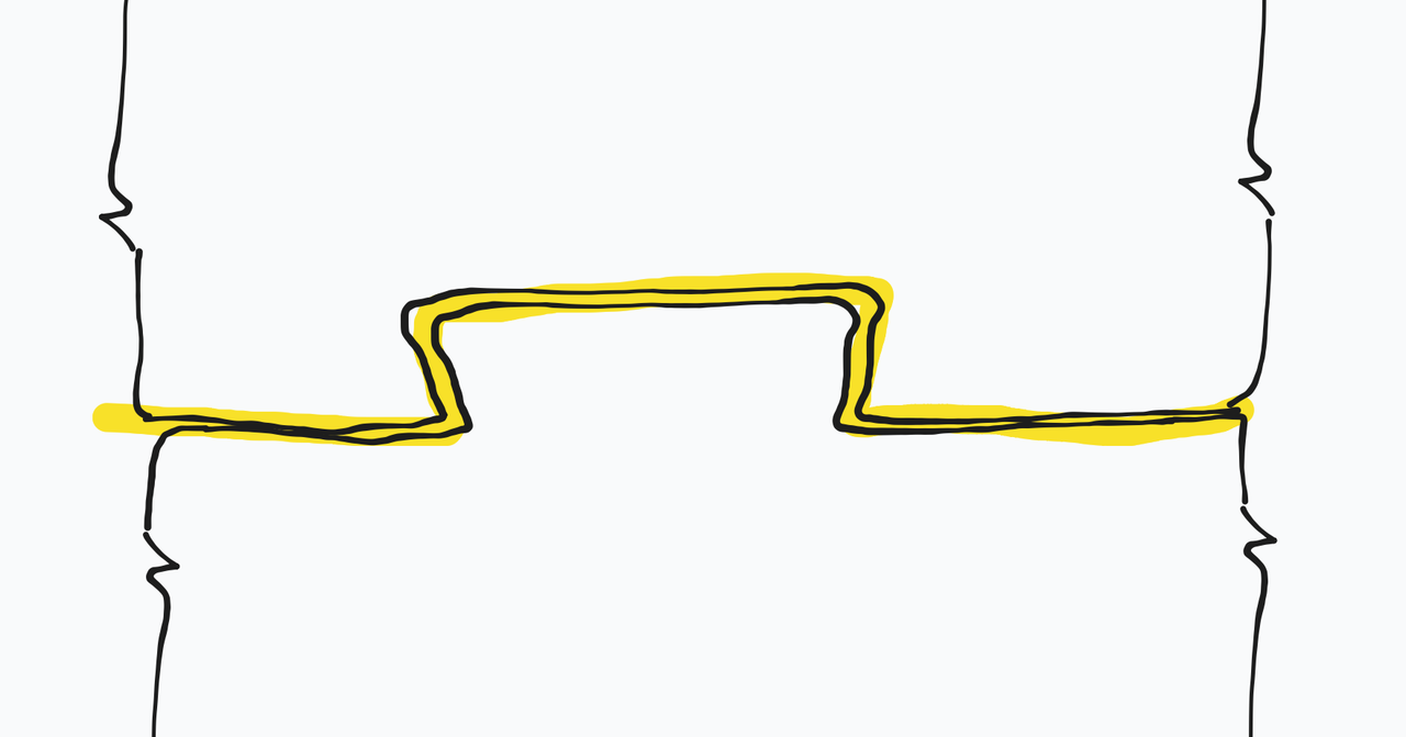
But why did it work out that way?
Will it work for resin printers, or do we have less wiggle room with that process? When Adam Savage set up his Formlabs Fuse nylon SLS printer, their first snap-together parts did not work because there is no flex in that material. (I appreciated them sharing that fail learning experience.)
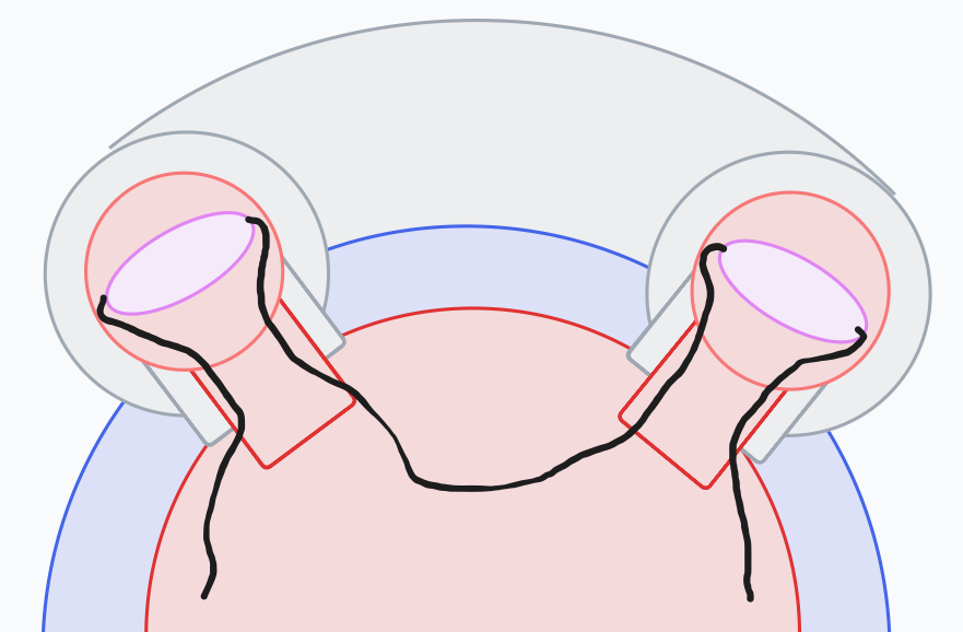
It makes sense that the angles of the hole collars around the ball make the rope into a big clip. This is also why the bigger parts are harder to coax into place.
LED wire is threaded through the inside like this.
Hemisphere coupler
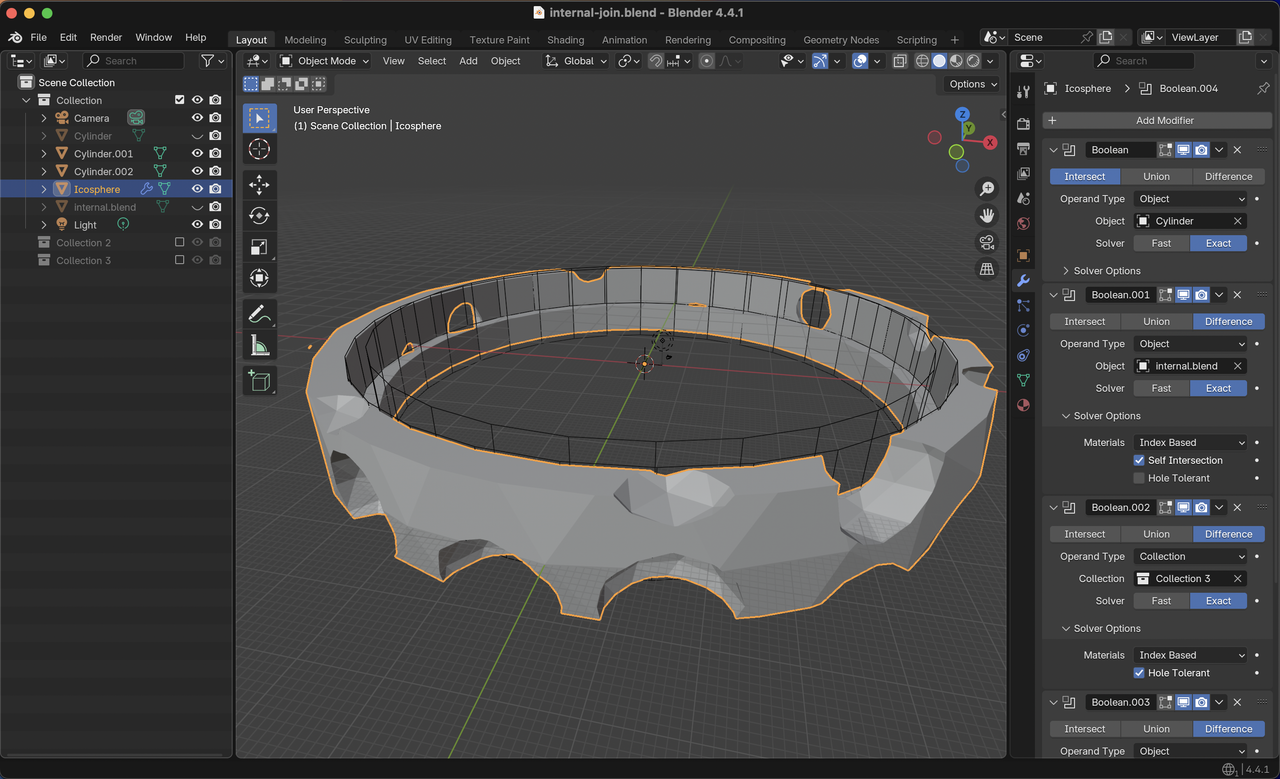
Blender setup for the part that holds the two hemispheres together. Part created with several Boolean modifiers.
Base shape: Icosahedron sized to fit within walls of the inner structure.
- Intersect: wide cylindar with desired height
- Subtract: inner structure, so the part fits within the inner structure
- Subtract: 32-sided cylindar through-hole to leave room for battery and access the bottom wires
- Subtract: cylindar placed so that the platform is centered in the sphere
- Subtract: several icosahedra to leave room for wires to go up or down
Note: it would have been more reusable to build these shapes with parameters in the web app, but Blender proved good enough to make the one part that I needed.
Electronics platform
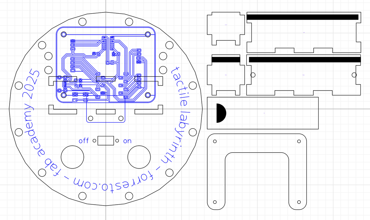
This is the platform to hold circuits, switch and battery. It was satisfying to use the laser cutter with the newly-replaced tube. I started with a cardboard version to test the fit, and then moved to 3mm plywood. I included extra holes in the platform to make it easier to deal with known and unknown unknowns.
Todo
Next on my mind...
😅
- ← Previous
Week 17. Four Axis Milling - Next →
Tactile Labyrinth